
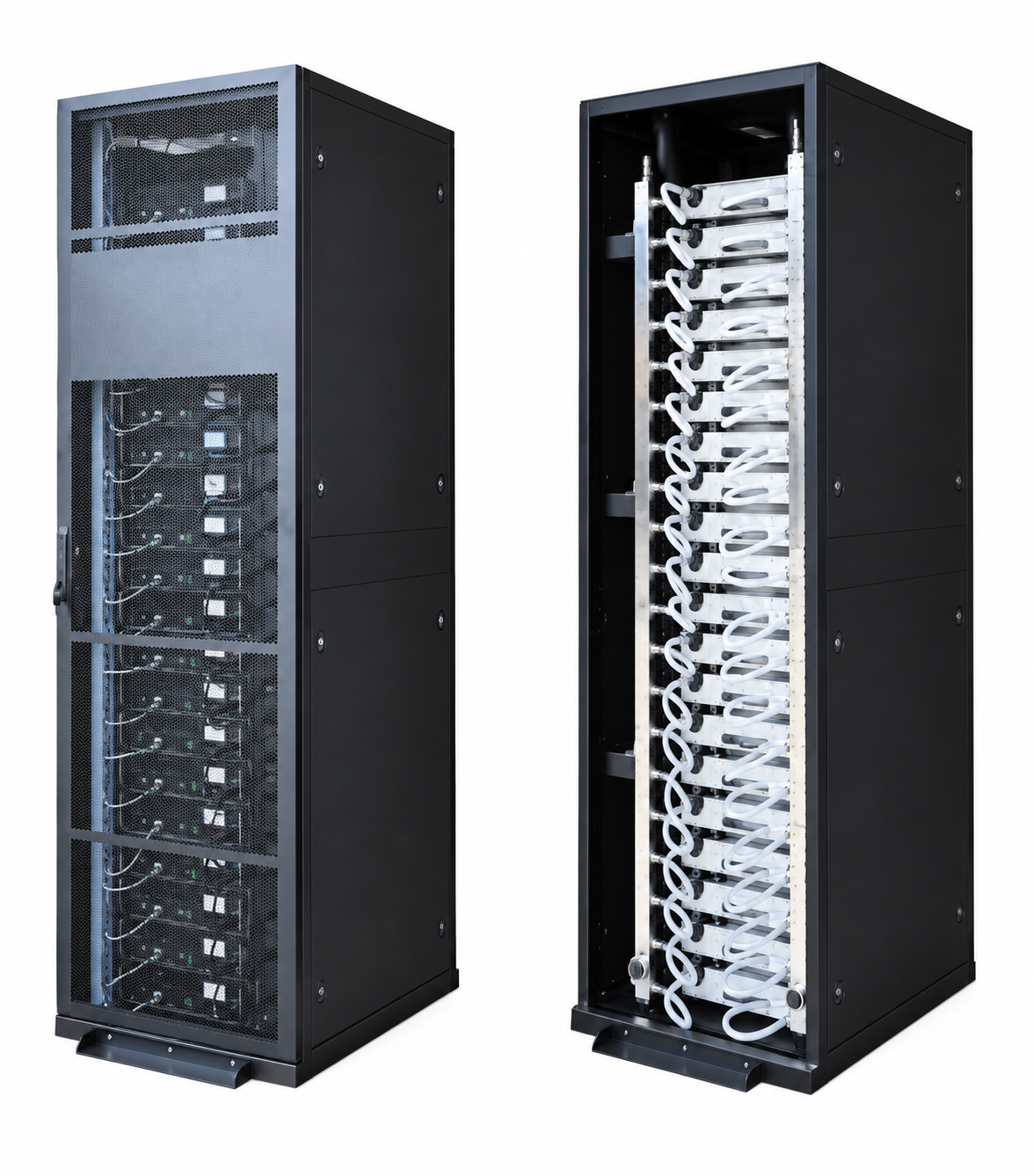
LIQUID COOLING HARDWARE
Cooling hardware for the spaces between the system and the rack.
Selected rack-level manifolds, quick disconnects, cold plates, sensors and related connection hardware coordinated to customer drawings and specifications.
A PRACTICAL SYSTEM VIEW
Liquid cooling becomes real at the connection points.
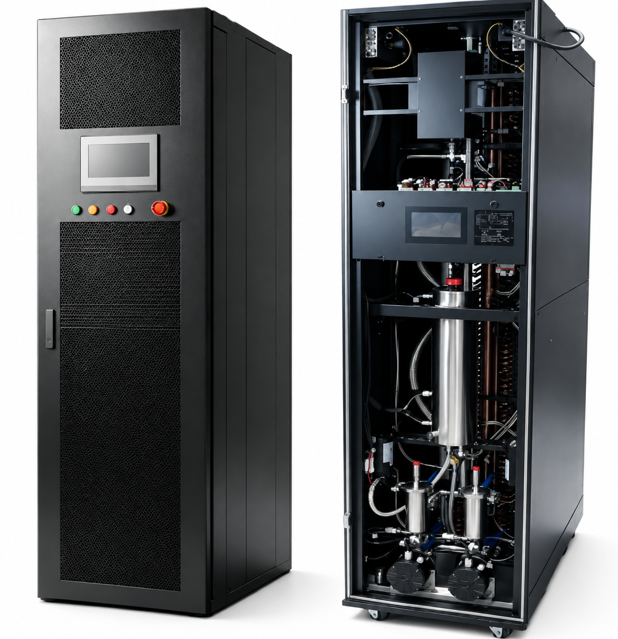
A CDU is only one part of the installation. Manifolds, hose routing, couplings, cold plates and monitoring points must work together within the project’s interface, space and service requirements.
01 / SYSTEM CONTEXT
From CDU to rack.
A clear distribution and connection path helps define the interfaces, hardware and checks required before delivery.
Component configuration and final scope depend on customer drawings, site interfaces and operating requirements.
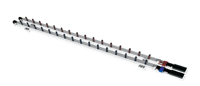
Distribution manifold for rack-level liquid cooling connections.
02 / HEAT TRANSFER
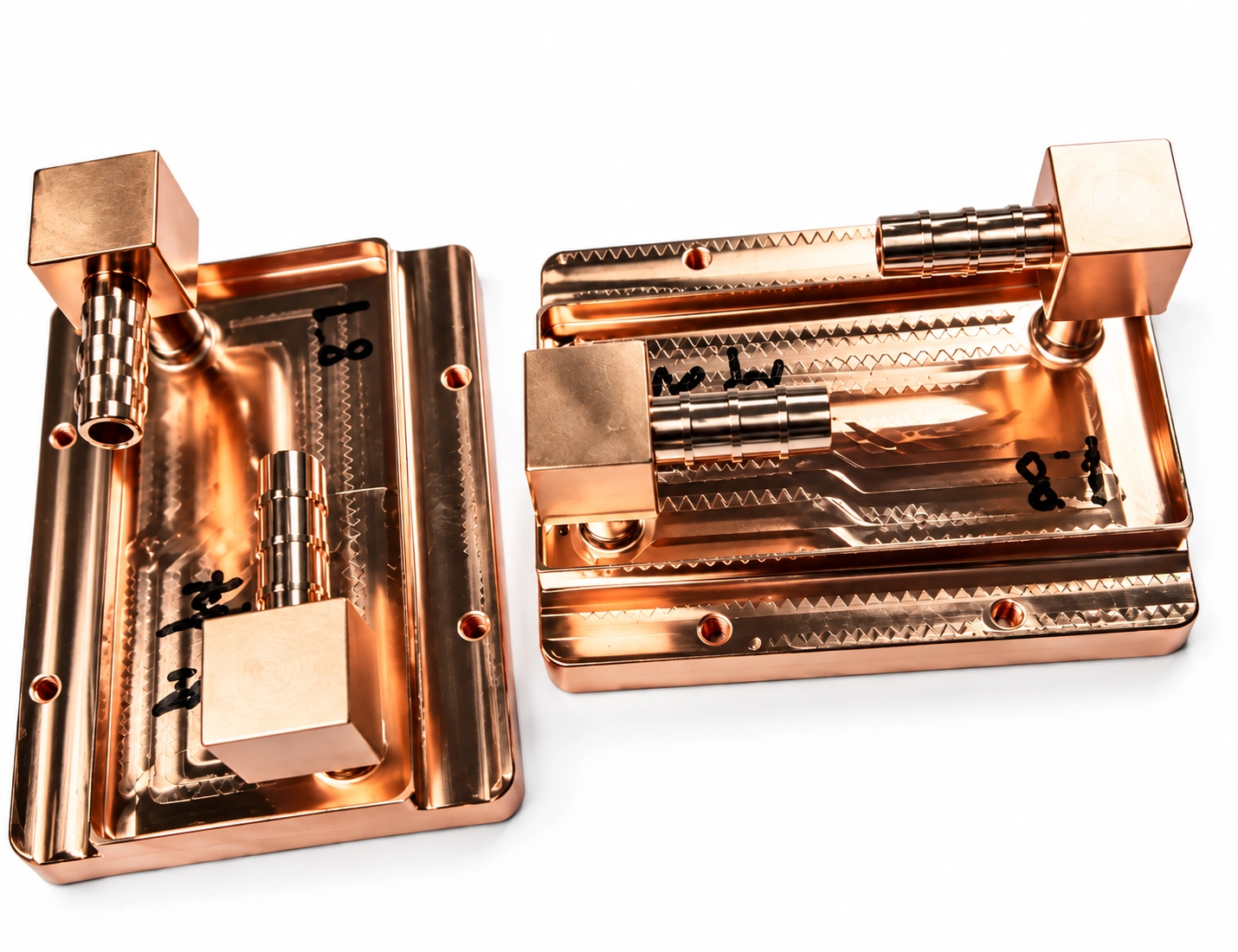
Cold plates shaped around the application.
Vacuum-brazed, microchannel and embedded-pipe cold plate configurations can be considered according to the required interface, heat-transfer path, material and available installation space.
03 / DISTRIBUTION
Distribution between the cooling source and the rack.
CDU and manifold interfaces organize the coolant path and provide defined connection points for rack-level liquid cooling hardware.
04 / SERVICEABLE CONNECTIONS
Quick disconnects for real installation constraints.
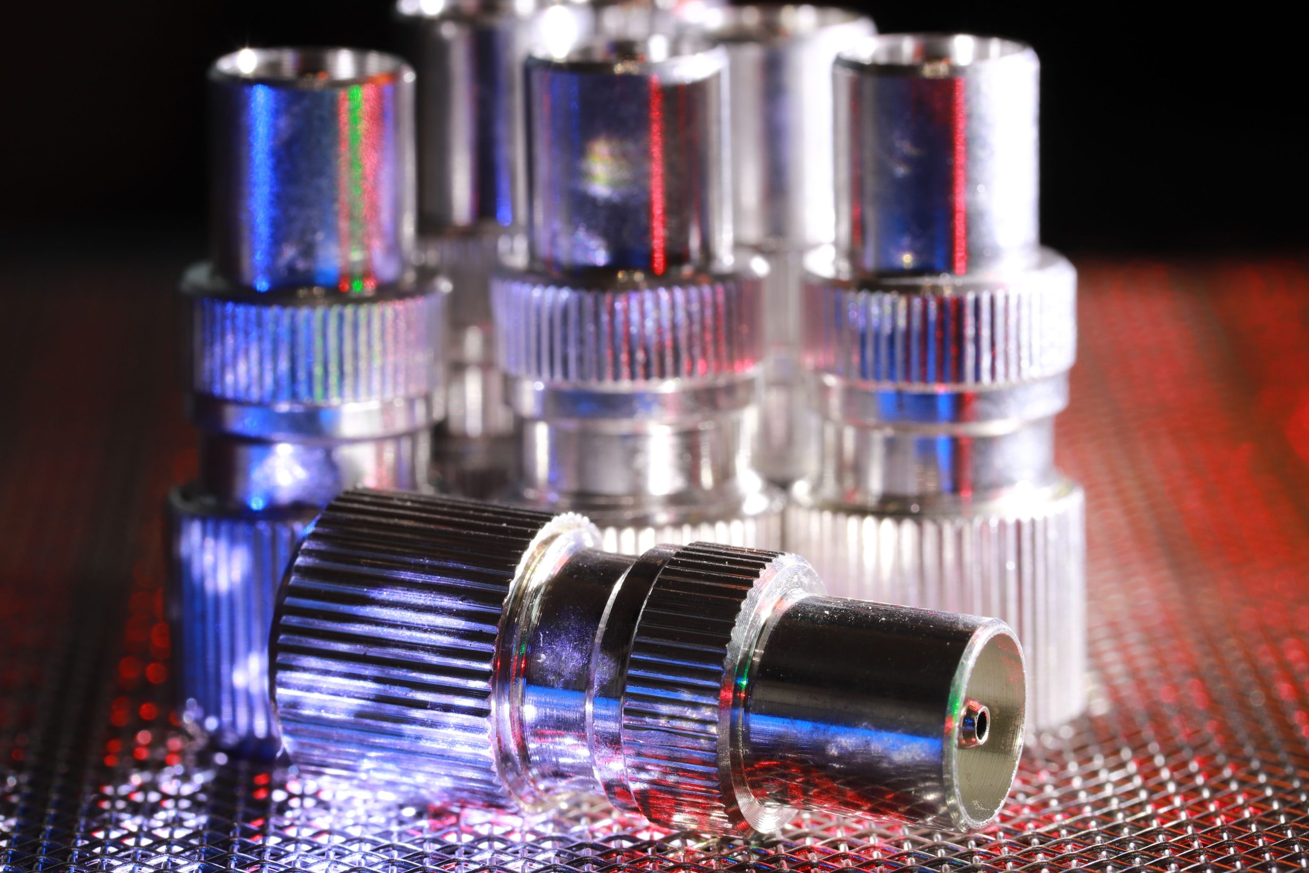
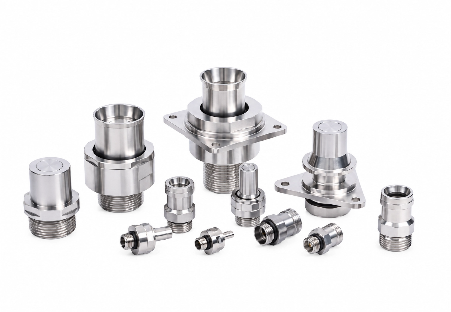
UQD and UQDB coupling options can support serviceable liquid cooling connections where flow requirements, routing, access and interface compatibility must be reviewed together.
05 / MONITORING
Visibility where the system needs it.
Selected pressure, temperature, humidity and leak-detection sensors can support monitoring requirements around the cooling installation.
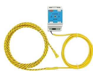
Leak detection
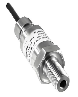
Pressure monitoring
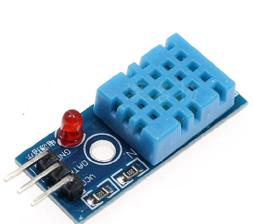
Temperature / humidity
TECHNICAL REFERENCE
Reference data for preliminary selection.
Data is provided for preliminary reference only. Final selection must be confirmed against coolant, temperature, pressure, flow rate, port, sealing material and operating conditions.
| Model | Port | Working pressure | Rated flow | Cv |
|---|---|---|---|---|
| UQD02 | 1/8 in | 20 bar / 290 psi | 2.1 LPM | 0.33 |
| UQD04 | 1/4 in | 16 bar / 232 psi | 6.4 LPM | 1.37 |
| UQD06 | 3/8 in | 6.9 bar / 100 psi | 11.4 LPM | 2.37 |
| UQD08 | 1/2 in | 6.9 bar / 100 psi | 17.8 LPM | 5.32 |
PARTNER-SUPPORTED APPLICATION REFERENCES
Different environments. A shared need for practical coordination.

Data center cooling retrofit
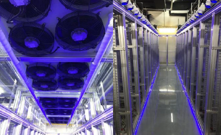
Cooling infrastructure
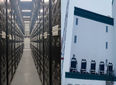
Industrial thermal management
These partner-supported application references illustrate relevant operating environments. Images are shown for context; final scope and performance depend on each customer’s site and project requirements.
START A PROJECT CONVERSATION
Have a liquid cooling hardware requirement?
Send us your drawings, interface details or project requirements. We will review the information and help identify a practical next step.